V3 Logic Technology
Air-Cooled or Air-Sourced Heat Pump Condensers

Compressors
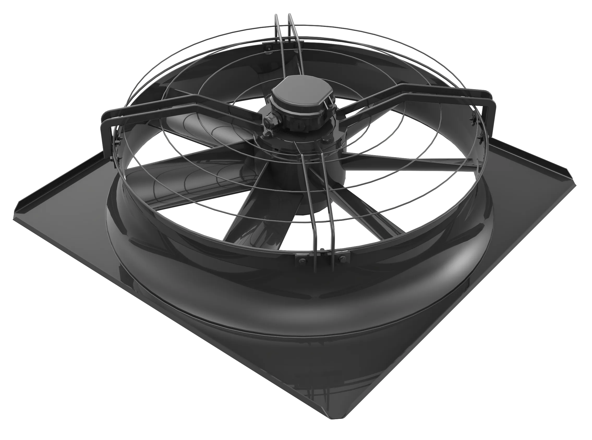
Condenser Fan
EC-Spider Fan
Water-Sourced Heat Pump Systems

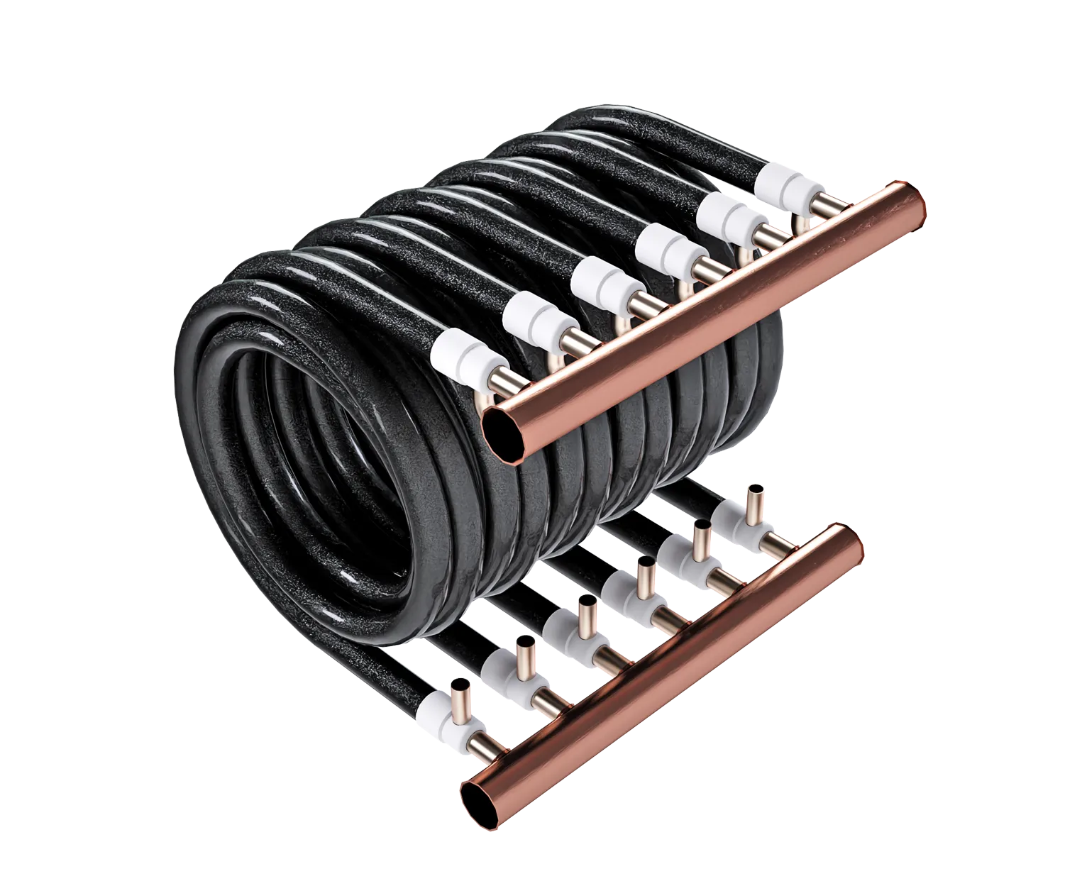


Compressors
EC-Spider Fan
Our V3 Logic smart head pressure control delivers optimal performance with its variable speed compressors
Traditional systems address part load conditions with unloading techniques either by using multiple compressors or by using digital compressors. These solutions are inefficient because high compressor efficiency cannot be maintained at part load or because the load matching ability is limited.
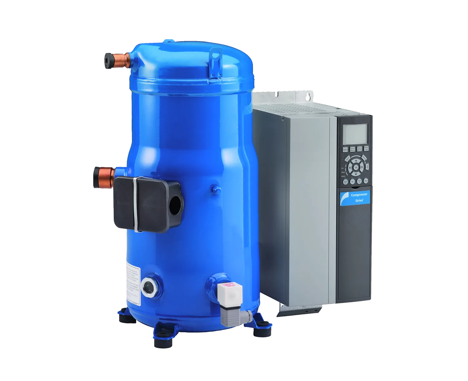
The VZH compressor made by Danfoss, designed to maintain high-isentropic efficiency, has the inherent benefit of precisely and continuously matching the load by operating from 30 Hz to 90 Hz. With no excess evaporator and condenser capacity under part load, the compressor COP is higher and delivers significant energy savings. Also, its continuous operation means less cycling and system stress, higher reliability and a longer lifespan. Helped by the Annexair unit PLC, the supply desired setpoint can be exceptionally precise with an accuracy of 1.0°F.
Additional savings are also achieved because the power factor remains above 0.90 regardless of the load; drive controller logic ensures soft starts that reduce inrush current. Depending on project location, V3 Logic energy savings can reach 15 to 35% versus conventional systems.
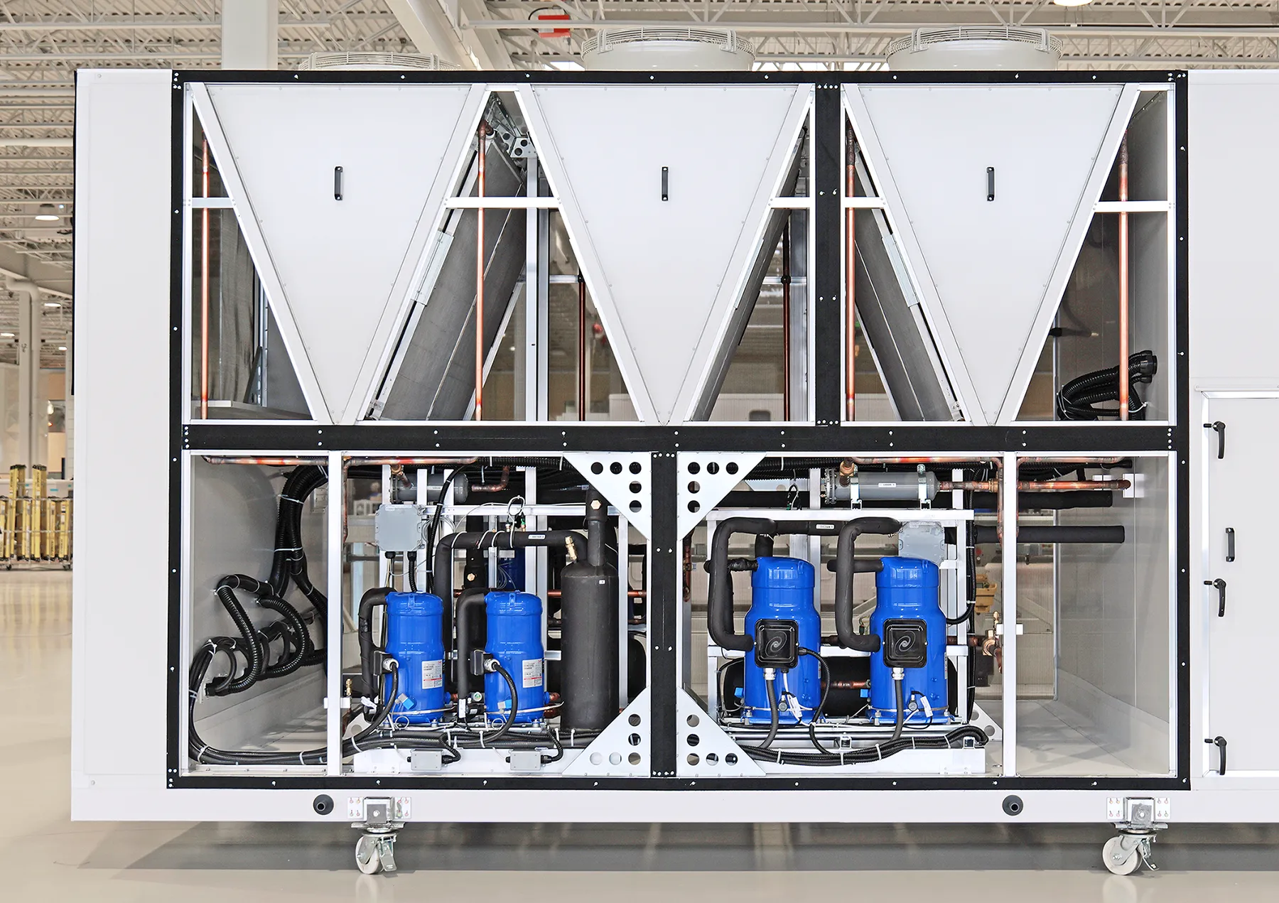
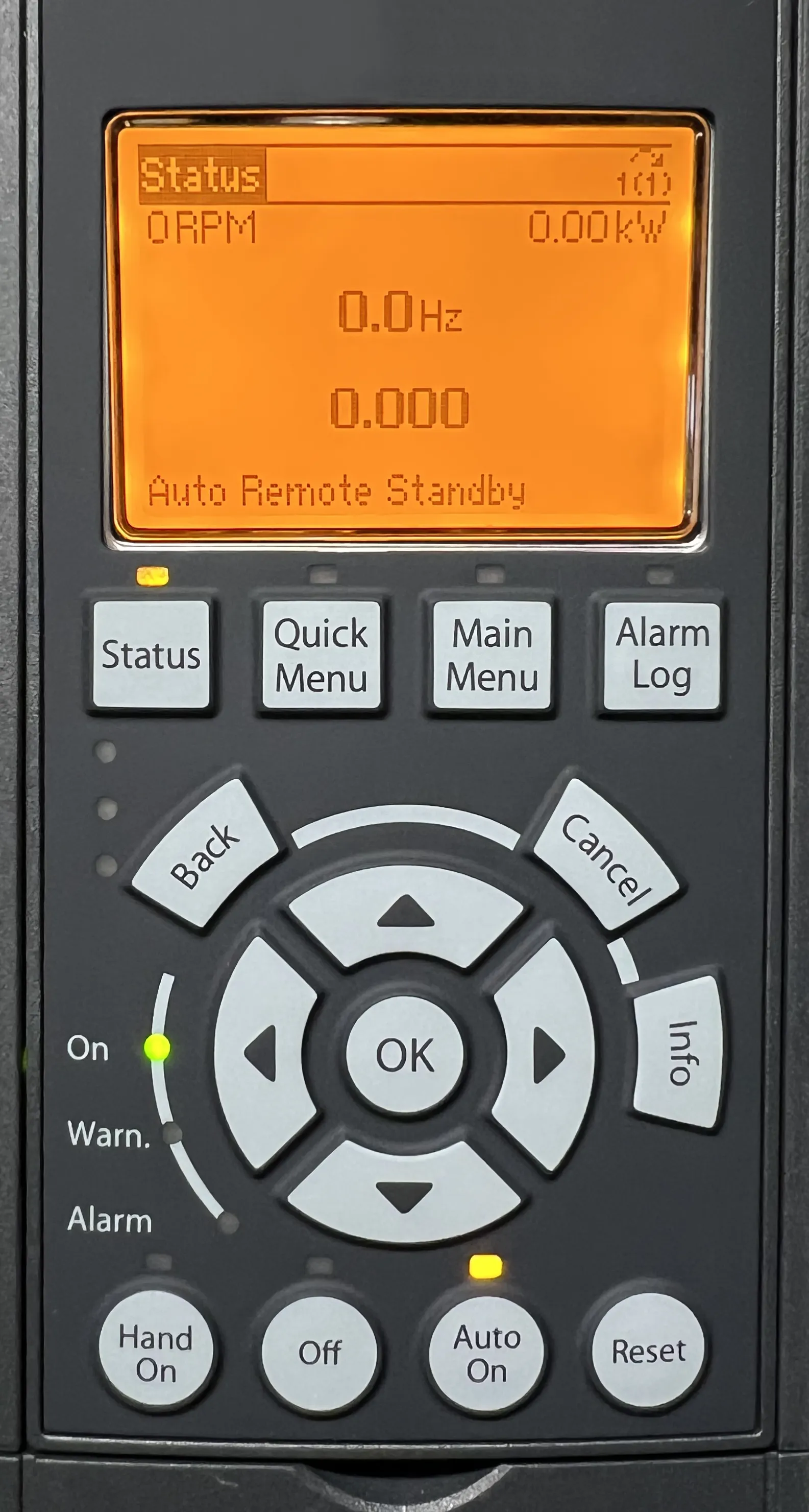
Each variable speed compressor comes equipped with a factory programmed VFD keypad that graphically displays multiple parameters: Hertz, amps, load capacity %, etc. It’s a great tool for monitoring, troubleshooting and maintenance. These values are also displayed on the unit PLC and accessible to the BMS via BACnet or LonWorks.
System designed
for energy savings
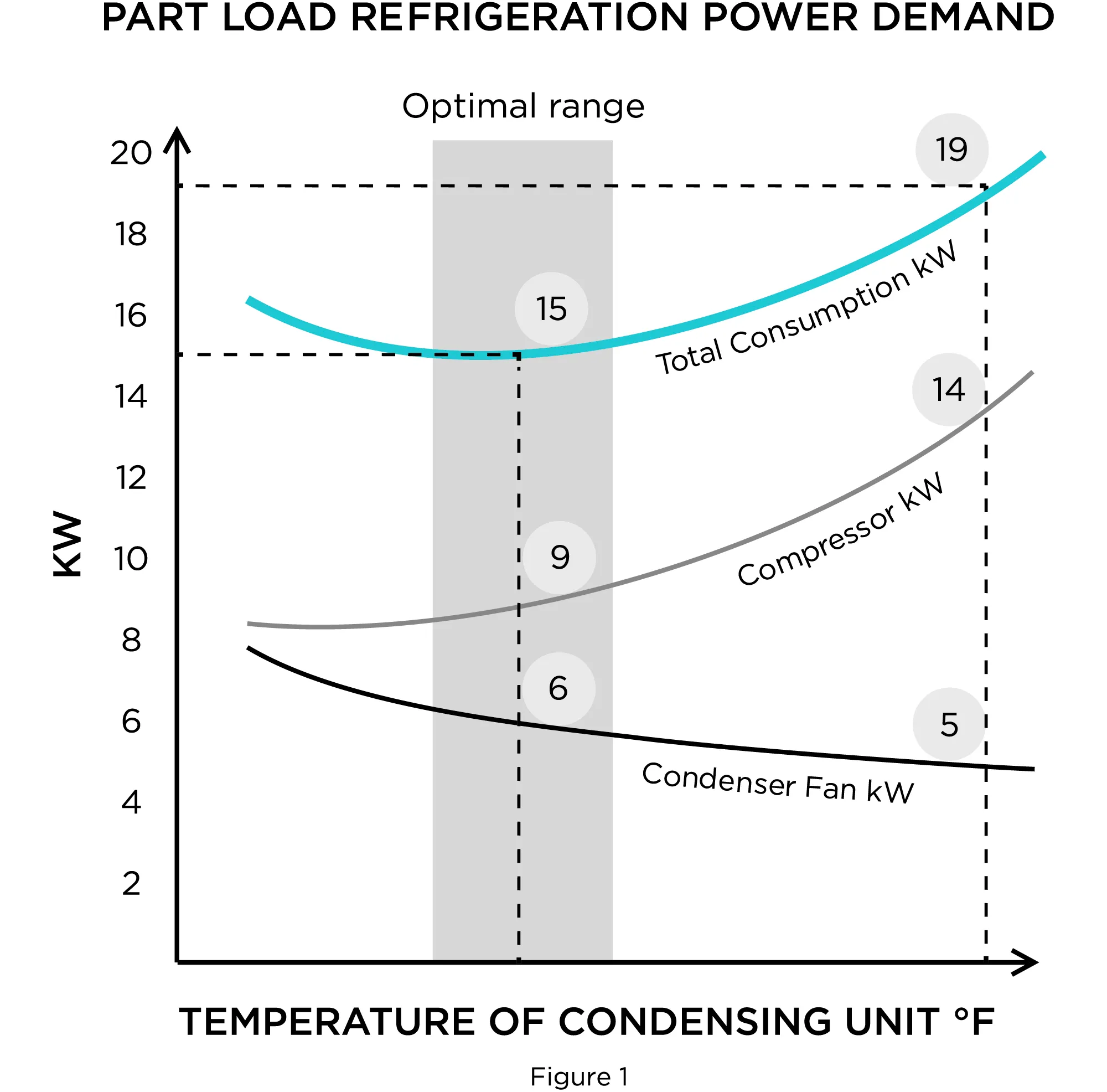
All Annexair cooling package models come with a smart head pressure control logic that modulates condenser fan speeds to keep the compressor motors at their perfect operational pressure level. These critical components – nicknamed “the Combo” by Annexair’s engineering team – perform smoothly together through synchronicity. This unique concept consumes the least amount of energy and delivers maximum comfort by always running in the optimal range.
Figure 1 represents the power consumption for the refrigeration system while in operation (blue line). The optimal range (grey zone) is the ideal zone where the additions in kW from the compressors and fans are at their lowest.
Super-efficiency variable
speed condenser fans
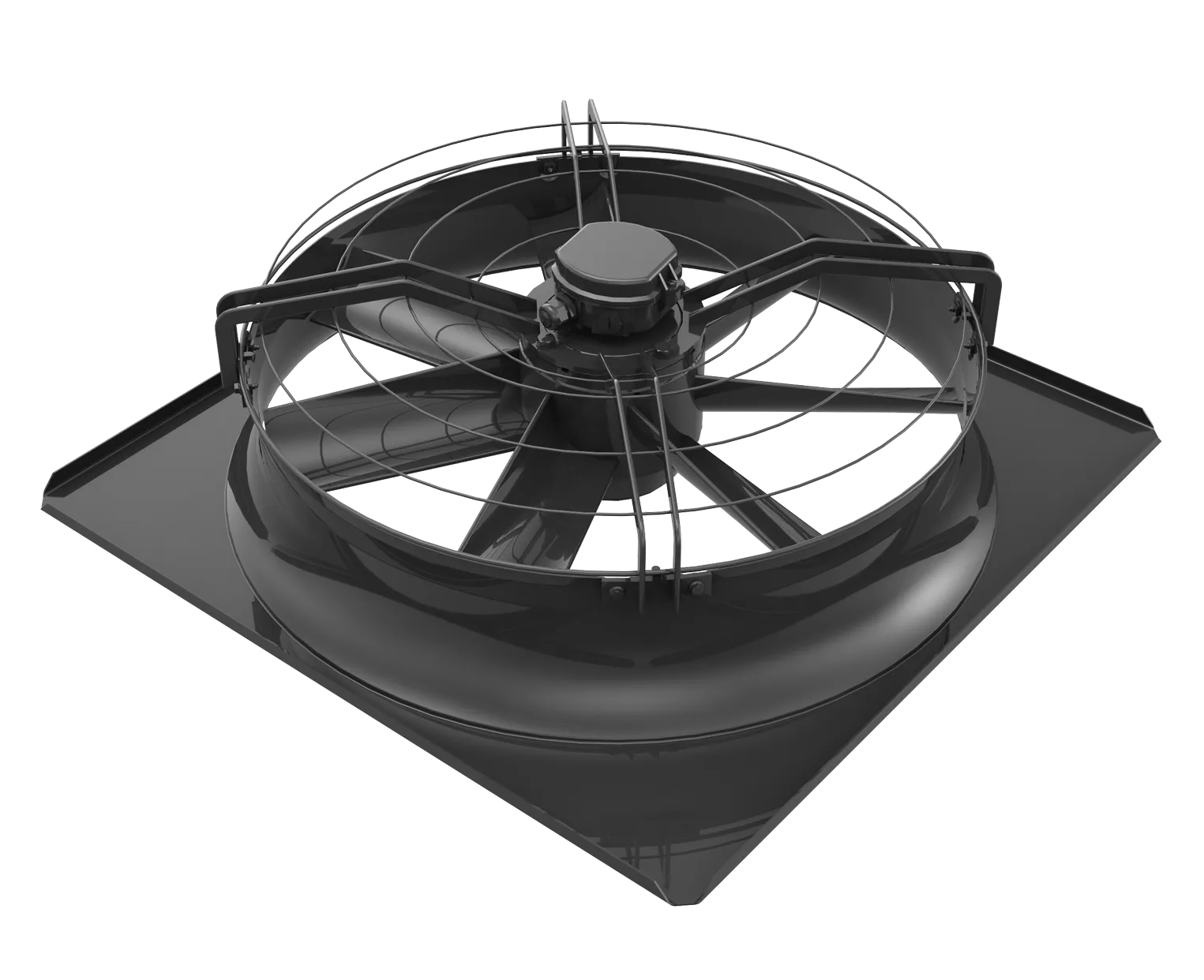
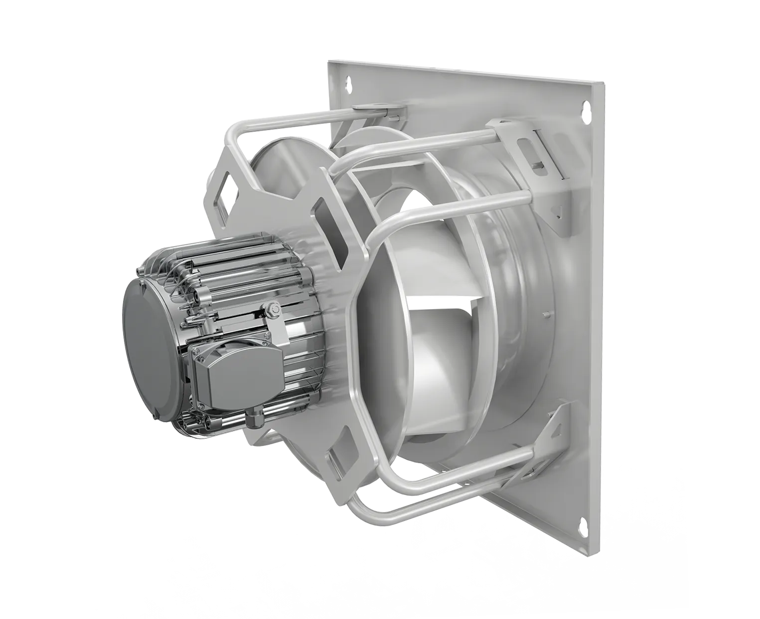
Variable speed condensing fans are a major component of our V3 Logic Technology. Variable voltage controllers provide 100% fan speed control. The unit’s PLC controller will vary the fan speed to maintain the compressor’s safety pressure in relation to outdoor air temperature. When necessary, each bank of fans will run together at the same speed to ensure a perfect airflow balance across the entire surface of the coils. Meanwhile, lower noise levels are achieved because the condensing fans will rarely operate at full speed.
Engineered to minimize energy costs
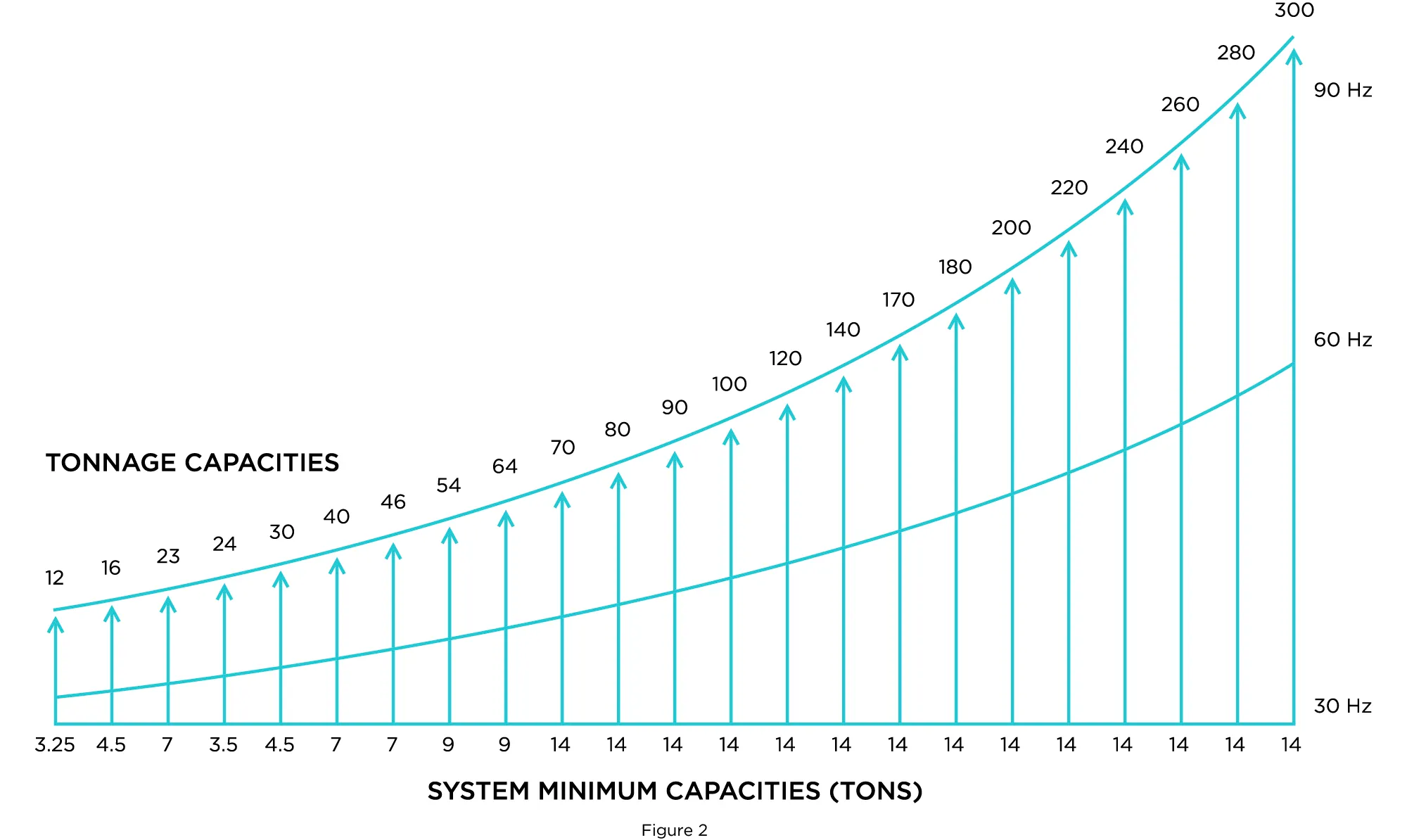
We design all of our condensers to radically reduce energy consumption and eliminate all peak loads at unit startup, helped by our soft-start compressors and their 30 Hz to 90 Hz modulating capability. For example, a 30-ton unit will modulate from 4.5 to 30 tons, a 64-ton unit will modulate from 9 to 64 tons and a 180-ton unit will modulate from 14 to 180 tons.
Figure 2 demonstrates the modulating capacities of our ACCUportfolio ranging sizes from minimum to maximum ton capacities.
Designed for maximum comfort
Designing an affordable refrigeration system that delivers increased comfort and savings is a challenge. By using variable speed compressors and variable speed condenser fans in unison, we have created the perfect sequence to maintain comfort levels and avoid wasting energy.
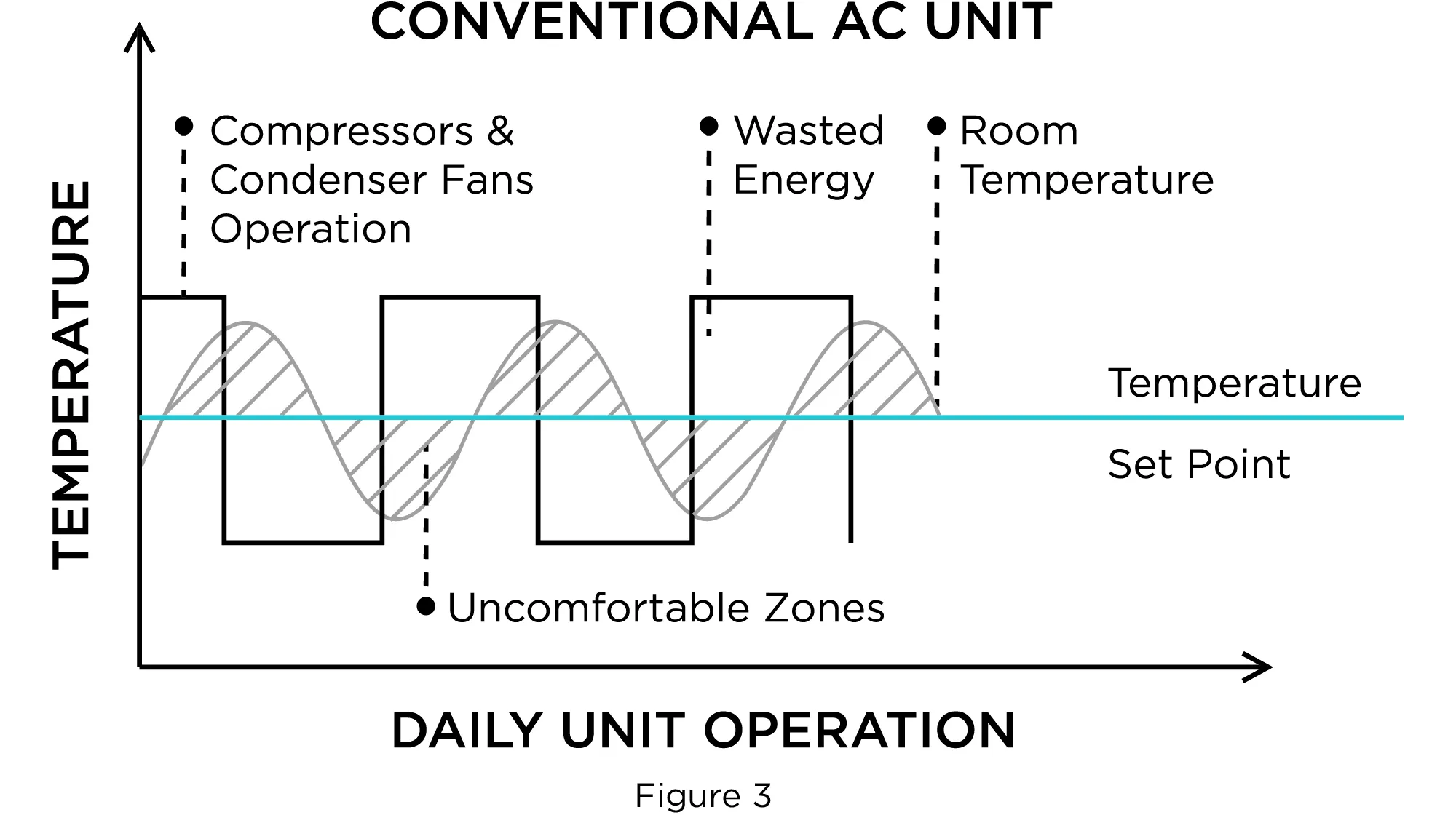
Figure 3 shows how conventional AC units continuously cycle on and off, wasting energy and affecting comfort levels.
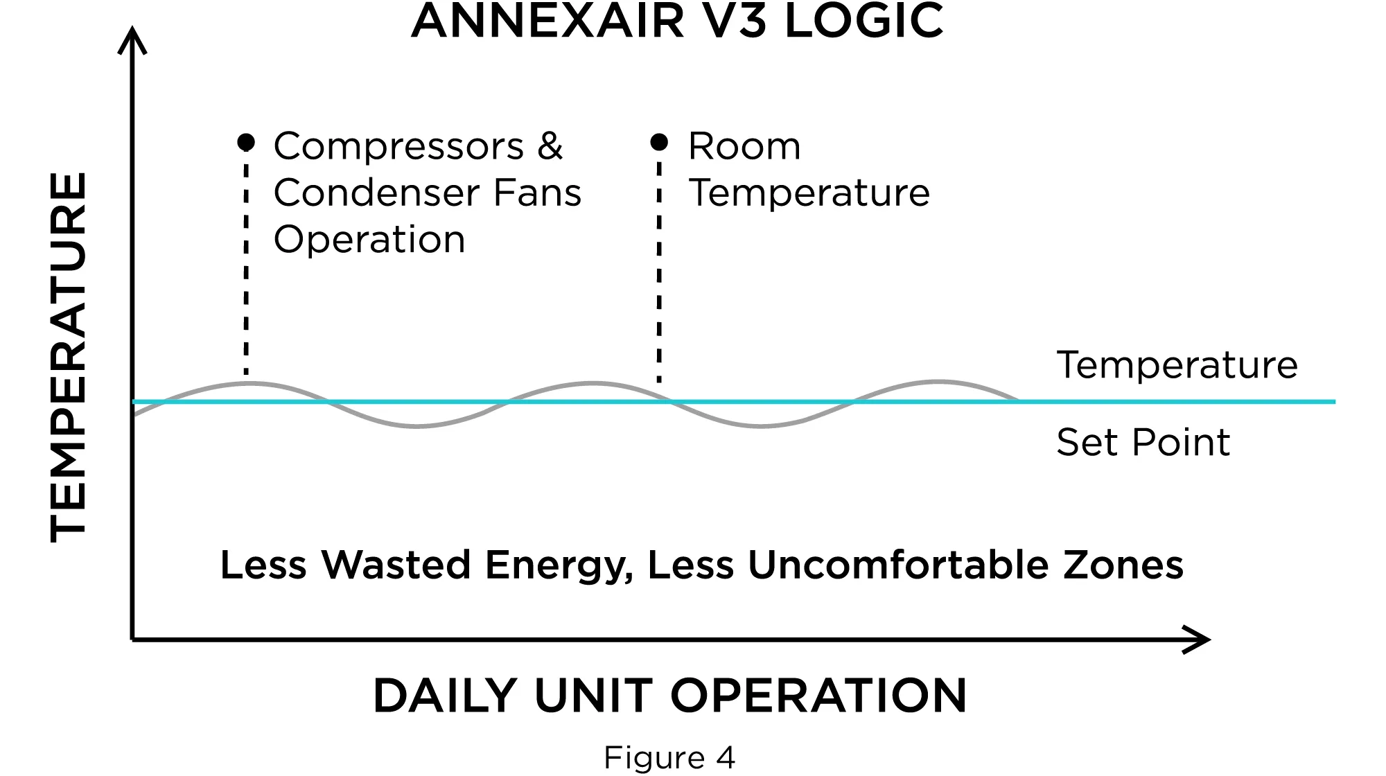
Figure 4 illustrates how our V3 technology requires less power to maintain comfort levels and how it eliminates ON/OFF cycling. Supply temperature can be held at ± 1.0°F of desired setpoints. As a result, annual unit operating costs are significantly reduced.
Full load vs part load
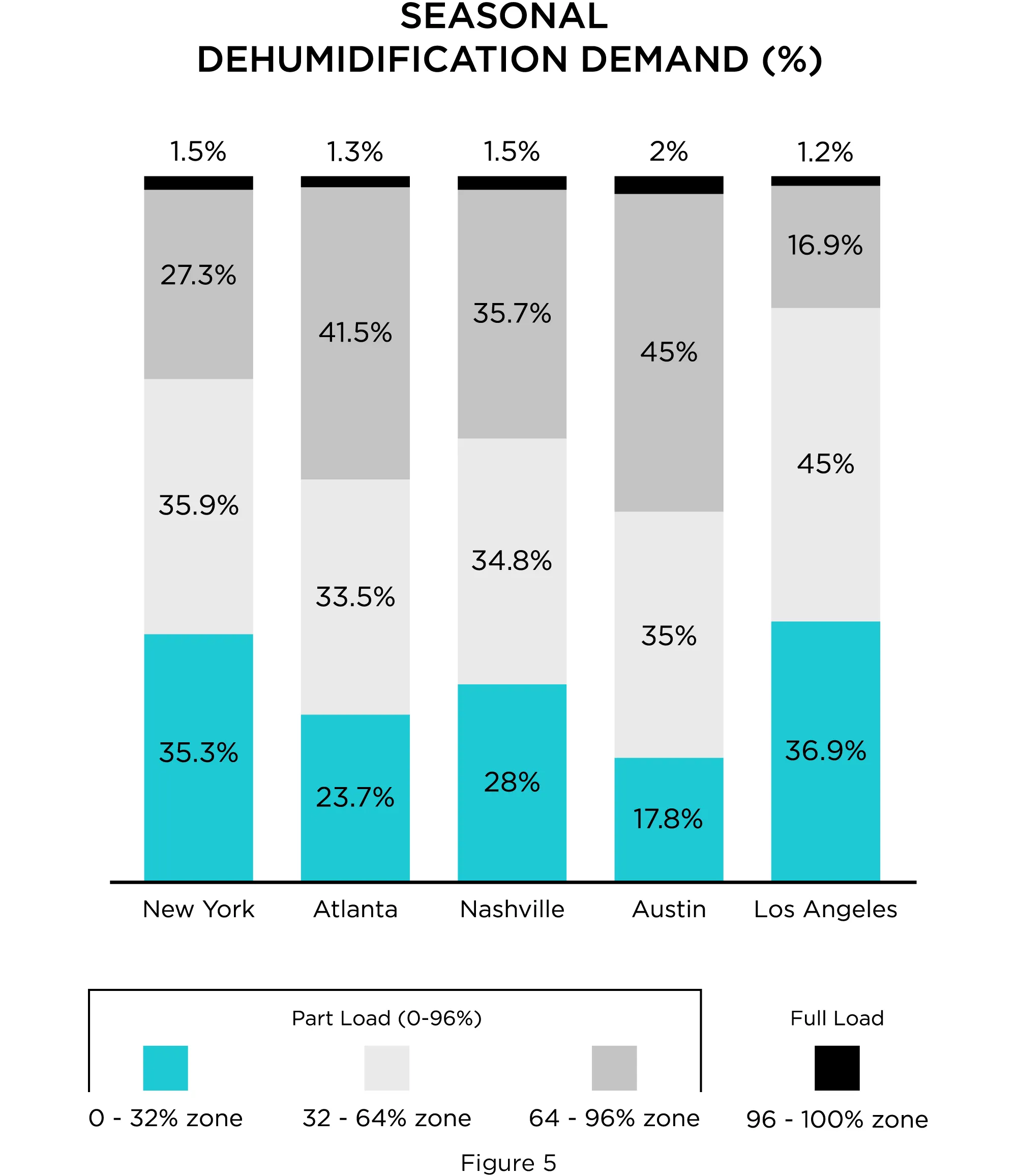
Even though units are designed for full-load operation, the reality is that they run most of the time in part-load operation. Units that cannot match design requirements with a certain accuracy result in wasted energy when working at part load. Figure 4 demonstrates the actual full load vs. part load requirement for 5 major cities in the United States. The graph represents an analysis of 25 years of bin data for each city collected from ASHRAE weather data and compiled to demonstrate the percentages of full load and part load operation. Full load operation is maintained for a maximum of 2% during the year while the remainder is considered part load operation. Part load capacity ranges have been divided into 3 zones represented by different colors. Considerable energy savings are obtained due to the impressive quantity of hours at part load.
Figure 5 - Digits in columns (%) represent the annual outdoor air temperature frequency of operation that exceeds 50°F dew point. Take note that the full-load zone (dark gray) has been defined for systems operating between 96 to 100% of ASHRAE city design condition; 96% and below is defined as part load zones. Data is based on ASHRAE 2009 Weather Viewer Dew Point Bin Data.
